Ethernet Passive Optical Network Tutorial
EPON is a PON-based network that carries data traffic encapsulated in Ethernet frames. Unlike other PON technologies which are based on the ATM standard, it uses a standard 8b/10b line coding and operates at standard Ethernet speed. This lets you utilize the economies-of-scale of Ethernet, and provides simple, easy-to-manage connectivity to Ethernet-based, IP equipment, both at the customer premises and at the central office.
EPON Network Structure
A typical EPON system is composed of OLT, ONU, and ODN (Figure 1).

The OLT(Optical Line Terminal)resides in the Central Office (CO) and connects the optical network to the metropolitan-area network or wide-area network, also known as the backbone or long-haul network. OLT is both a switch or router and a multi-service platform which provides EPON-oriented optical interfaces. Besides the network assembling and access functions, OLT could also perform bandwidth assignments, network security and management configurations according to the customers’ different QoS/SLA requirements.
The ONU(Optical Network Unit)is located either at the end-user location or at the curb and provides optical interfaces which are connected to the OLT and service interfaces at users’ side such as voice, data and video.
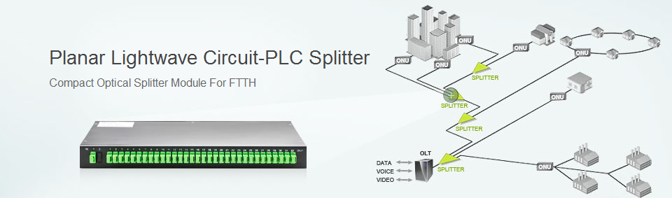
The ODN(Optical Distributed Network)is an optical distribution network and is mainly composed of one or more passive optical splitters which connects the OLT and ONU. Its function is to split downstream signal from one fiber into several fibers and combine optical upstream signals from multiple fibers into one. Optical splitter is a simple device which needs no power and could work in an all-weather environment. The typical splitters have a splitting ratio of 2, 4, 8, 16 or 32 and be connected to each other. The longest distance the ODN could cover is 20 km.
EPON Downlink and Uplink Technology
In an EPON the process of transmitting data downstream from the OLT to multiple ONUs is fundamentally different from transmitting data upstream from multiple ONUs to the OLT.
In the downstream direction, Ethernet frames transmitted by the OLT pass through a 1:N passive splitter and reach each ONU. N is typically between 4 and 64. This behavior is similar to a shared-medium network. Because Ethernet is broadcast by nature, in the downstream direction (from network to user), it fits perfectly with the Ethernet PON architecture: packets are broadcast by the OLT and extracted by their destination ONU based on the media-access control (MAC) address (Figure 2).

Figure 2. Downstream Traffic in EPON
In the upstream direction, due to the directional properties of a passive optical combiner, data frames from any ONU will only reach the OLT, and not other ONUs. In that sense, in the upstream direction, the behavior of EPON is similar to that of a point-to-point architecture. However, unlike in a true point-to-point network, in EPON data frames from different ONUs transmitted simultaneously still may collide. Thus, in the upstream direction (from users to 13 network) the ONUs need to employ some arbitration mechanism to avoid data collisions and fairly share the fiber-channel capacity (Figure 3).

Figure 3. Upstream Traffic in EPON
EPON and ADSL Comparison
The requirement of bandwidth is increasing crazily with the incoming of digital age. Therefore the current high speed copper cable ADSL (Asymmetric Digital Subscriber Line) cannot meet our needs longer. The bandwidth of ADSL is limited to only a few megabit per second and the upstream and downstream bandwidth are not equal either. However, optical fiber has larger bandwidth and superior transmission capability which reaches gigabit per second. Hence, optical fiber used in access network is the future trend. And since Ethernet is low cost, uncomplicated widely-used in current network, and its application is very popular nowadays. So it is not hard to see that it is feasible and economical to combine them together. EPON technology combines a mature Ethernet technology and high-bandwidth PON technology, which is an ideal access method to achieve integrated services. In the future, highbandwidth business will surely drive up existing EPON which has the rate of 1.25Gbps in both the downstream and upstream directions.
EPON Technical Advantages
EPONs are simpler, more efficient, and less expensive than alternate multiservice access solutions. Key advantages of EPONs include the following:
With the growing of EPON technology, interaction standards and EPON devices, EPON has entered the large scale application phase driven by the huge market demands. EPON is fit for the access market which is at the end of the fibers and which has a certain density and these markets include FTTH, FTTP, FTTB, FTTN etc.
EPON becomes a very economical and effective broadband access solution because of its predominance in equipment investment and also the operations, maintenance and etc. It could be said that the EPON technology has become the developing direction of access network’s technologies in the future as an ideal solution for FTTH.
Read more »